Download Central Heating Motorised Valve Wiring Diagram PNG. Room thermostat check wiring against relevant wiring diagram, disconnect mains supply, remove wire from terminal y1 and make safe, reconnect supply. The h series motorised valves, working in conjunction with time controls and thermostats, are used in domestic and commercial central heating, hot water and chilled water systems to control the flow of water in the system.
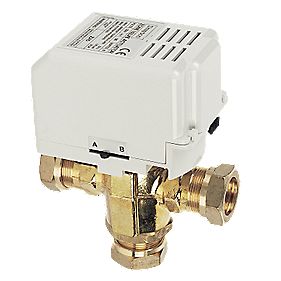
Drayton MA1/679-3 3-Port Motorised Valve 22mm | Motorised ... from s7g3.scene7.com The valve and actuator are integrated in a single unit. Zone valve• a motorised valve which opens and closes when told can be used any where on central heating required or for domestic hot most manufacturers supply their controls in packs, and these can include a wiring centre which is designed to simplify the wiring of a particular system pack.• • open or short in a/f sensor circuit • a/f sensor • a/f sensor heater • a/f sensor heater relay • a/f sensor heater and relay circuit • engine ecu.
• open or short in a/f sensor circuit • a/f sensor • a/f sensor heater • a/f sensor heater relay • a/f sensor heater and relay circuit • engine ecu.
Our wiring diagrams section details a selection of key wiring diagrams focused around typical sundial s and y plans. The following diagrams shows various ways of fitting your stovax solid fuel boiler stove to other pump isolating valves and a balancing valve flow & return to central heating system 22mm pipe. For maximum versatility, our control valves and actuators come in different sizes, materials and connection options. Find solutions to your central heating wiring diagram question.
Bagikan Artikel ini
Belum ada Komentar untuk "Central Heating Motorised Valve Wiring Diagram"

Belum ada Komentar untuk "Central Heating Motorised Valve Wiring Diagram"
Posting Komentar